W³ ?
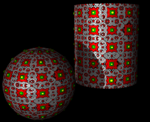
This material has evolved from the cell based displacement experiments by K. Pettersen, M. Kappenburg and others. It uses as it's basis the VSL cell operator; this operator produces repeating patterns that can be altered in many ways including fractal noise based variations. The result is a material that can be altered from perfectly consistent repeats of the cells to something that is no longer recognizable as a cell-based pattern.
The material presented here is the result of experimentations that began to resemble control panel buttons with a bit of a hand-drawn look. Additional experiments have resulted in what is shown in the image to the right; something more resembling renaissance period fabric.
An attempt has been made to make the resulting standard interface for the material as intuitive as possible and to be featured, but not contain any unnecessary components.
Included here is an explanation of the standard interface controls and additionally, a brief list of functions of the the individual VSL components and a more in-depth explanation of each component's use in the material. This documentation assumes at least, a basic working knowledge of Realsoft3D; how to create and alter the properties of NURBS, SDS and VSL material objects.
Usage and Controls
This Material uses displacement mapping, thus, suitable target objects include all NURBS mesh objects and SDS objects with type set to “Smooth to NURBS”.
Many factors influence acceptable point counts; displacement values, object quality setting, etc.. A NURBS sphere 50 by 27, set to the default quality “2”, and an SDS sphere 10 by 5, default quality , are sufficient for the material's default values.
To use the material simply select a suitable object and make a “Default”-type mapping of the material.
While lower point count displacement meshes can be made of SDS objects, more predictable mapping results are usually more easily obtained with NURBS meshes; this is especially the case for spherical objects.
For swept-type NURBS meshes, setting “phantom” end condition in the properties window results in more accurate mapping of the material.
For extruded NURBS meshes, select the mesh that is created by the extrusion process and select “Define UV” from the NURBS toolbar.
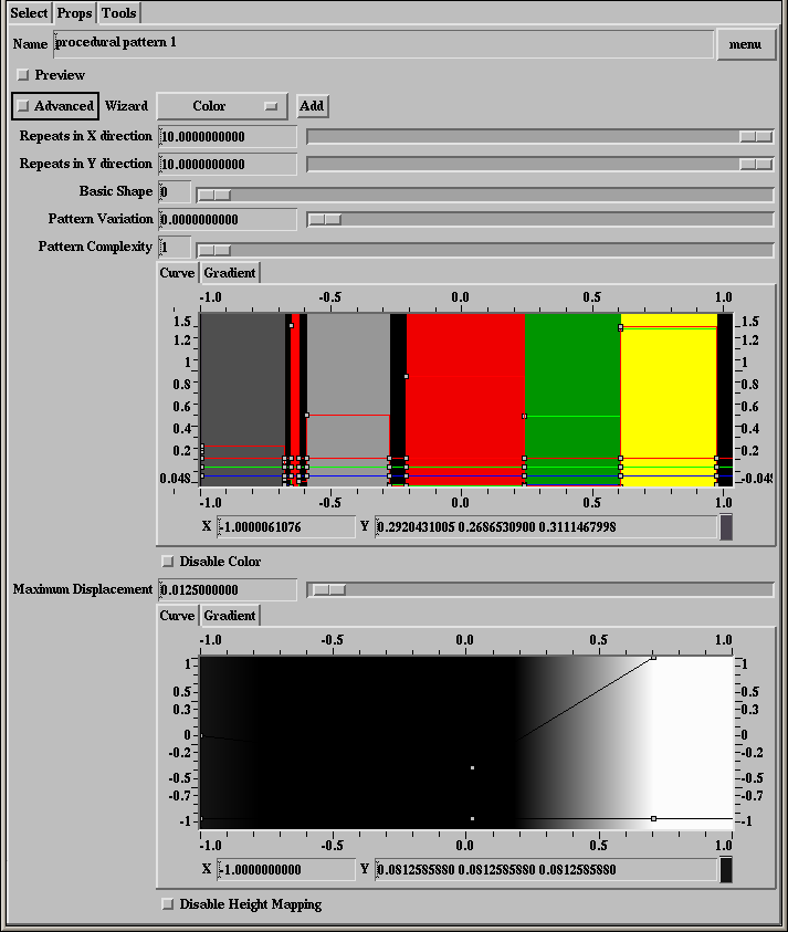
Repeats in X and Y direction sliders: Controls how many complete copies of the pattern will mapped across the mesh in the respective directions. This corresponds to the UV coordinates of the object.
Basic Shape: Determines the basic shape of the elements of the pattern, 0=sphere, 1=cube and 2=rounded cube.
Pattern Variation: Adjusts the amount of height variation in the pattern, it has the effect of shifting the curves that determine height and color with relation to where they show up in the “copies” of the pattern.
Pattern Complexity: Sets the number of times the pattern is subdivided.
Color Curve: Controls the colors that are used in the pattern, they are mapped in a mostly literal manner; the left end of the curve corresponds to the perimeter of each instance of the patten, the right end to the center.
Disable Color: Disables color mapping.
Maximum Displacement: This value should match the value set for the object that the material is being applied to; this is set under the “spec” tab in the object's “Property” window.
Height Curve: Nearly identical in function and application to the color curve but, only having one control curve, it determines the cross sectional height profile of the pattern instances.
Disable Height Mapping: Disables the displacement (bump height) mapping.
Basic VSL Explanation
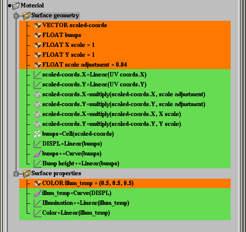
Surface Geometry Shader
Variables
scaled-coords: Temporarily holds the adjusted coordinate values.
bumps: Temporarily holds height map values.
X scale: The number of repeats in the X direction; initialized to 1.
Y scale: The number of repeats in the Y direction; also initialized to 1.
scale adjustment: This number was derived by experimentation, it adjusts the default cell mapping so “1=1”.
Operations
Linear: Copies the UV based X and Y coordinates to the respective values of the “scaled-coords” variable. The X and Y coordinates are treated separately to provide for different quantities of repeats in the respective directions. This operation also shifts the Y coordinates so the pattern is centered, using a rectangular type NURBS object as a reference.
Operation-multiply (1st & 2nd occurrence): The scale adjustment being applied; the copied UV coordinates are multiplied by the “scale adjustment “ variable.
Operation-multiply (3rd & 4th occurrence): The variable “scaled-coords” is multiplied by the X and Y repeat variables to produce repeats of the texture in the respective directions.
Cell: The cell operator, this built-in function is the basis for this shader; here “scaled-coords” is brought into the cell operator as a single vector value and output to “bumps”, a float variable.
Linear: Copies the value of the “bumps” variable to the user created global channel “DISPL”.
Curve: Curve operator, determines the cross-sectional shape of the height mapped cells.
Linear: Adds the contents of the variable “bumps” to Realsoft's bump height channel.
Surface Properties Shader
Variables
illum_temp: Temporarily holds illumination values; initialized to 0.5,0.5,0.5.
Operations
Curve: Curve operator, determines the illumination and color of the various parts of the cells; takes DISPL as input.
Linear: The result of the curve operator, illum_temp, is added to Realsoft's “Illumination” channel.
Linear: The result of the curve operator, illum_temp, is copied to Realsoft's “Color” channel.
(Semi-)Advanced VSL Explanation
Portions from above are repeated for clarity; even where there is no additional information for the item.
Surface Geometry Shader
Variables
scaled-coords: Temporarily holds the adjusted coordinate values. Since the coordinates have to be adjusted to make them intuitive in the interface, a value of 1 representing one repeat of the texture, a vector type (three-value) variable is required to store the X, Y and Z coordinate values; although only the X and Y values are utilized.
bumps: Temporarily holds height map values. This variable is a float type variable (a single value) since height mapping is represented at any given point by only a single value.
X scale: The number of repeats in the X direction; initialized to 1. This variable will hold the user input values that will be multiplied by the adjusted coordinate value to determine the number of repeats of the pattern.
Y scale: The number of repeats in the Y direction; also initialized to 1. This is the same a X scale but for the Y coordinates and repeats.
scale adjustment: This number was derived by experimentation, it used to adjust the default cell mapping so “1=1”. A float-type variable initialized to a value of 0.04; it works for adjusting both the X and Y coordinate scale.
Operations
Linear: Copies the UV based X and Y coordinates to the respective values of the “scaled-coords” variable. Using the UV coordinates as the basis for mapping the material is what causes the material to be "wrapped" around the material in a fairly consistent manner. The X and Y coordinates are treated separately to provide for different numbers of repeats in the respective directions. This operation also shifts the Y coordinates so the pattern is centered, using a rectangular type NURBS mesh as a reference. To accomplish this, 0.5 is added to the Y coordinate, causing the pattern to be shifted "up" one-half of a mapping instance "height".
Operation-multiply (1st & 2nd occurrence): The scale adjustment being applied; the copied UV coordinates, "scaled-coords" are multiplied by the “scale adjustment “ variable. Again, at this point the mapping has been adjusted so an unmodified default mapping of the material, with X and Y Repeats set to the default 1.0, would result in a single instance of the mapping being mapped to a rectangular NURBS mesh.
Operation-multiply (3rd & 4th occurrence): The variable “scaled-coords” is multiplied by the X and Y repeat variables to produce repeats of the texture in the respective directions.
Cell: The cell operator, this built-in function is the basis for this shader; here “scaled-coords” is brought into the cell operator as a single vector value and output to “bumps”, a float variable. Only
Linear: Copies the value of the “bumps” variable to the user created global channel “DISPL”. This is one method of making a variable accessible by other shaders in this, or in other materials.
Curve: Curve operator, determines the cross-sectional shape of the height mapped cells. This curve is set to type “Boolean”in the curve's right-click menu; this results in abrupt transitions between the key points of the curve. Any type of curve can be implemented here but, boolean curves are likely to cause artifacting with high displacement values unless the material is used on a very high resolution mesh.
Linear: Adds the contents of the variable “bumps” to Realsoft's bump height channel. Note that the operation is set to “+” under the “General” tab for the operation in the “Property” window.
Surface Properties Shader
Variables
illum_temp: Temporarily holds illumination values; initialized to 0.5,0.5,0.5.
Operations
Curve: Curve operator, determines the illumination and color of the various parts of the cells; takes DISPL as input. This curve is set to type ”boolean”, in the curve's right-click menu; this results in hard-edged transitions between the between the key points of the curve in turn resulting in distinctly delineated bands of color. Any type of curve can be used here.
Linear: The result of the curve operator, illum_temp, is added to Realsoft's “Illumination” channel. Note that the operation is set to “+” under the “General” tab for the operation in the “Property” window.
Linear: The result of the curve operator, illum_temp, is copied to Realsoft's “Color” channel. This time, the value is copied to the channel, operation set to the default “=”, instead of adding it.